black iron pipe
Collapse
X
-
Oxygen / acetylene.
For about $20 - $30 you can probably replace the pipe seen in the pic. The thing about exhausts is that the constant heating and cooling causes corrosion on the material...more so than if it was just kept at room temp. The threads seize in pretty good. When I took mine apart it was there a long time and much rougher looking than yours. I used oxygen / acetylene and it came apart. That was a few years back now, and I had one section so rusty that I broke it pulling on it. FWIW.
Edit: Your pipe does look pretty good though....but ??Last edited by Mo; 04-17-2013, 06:32 AM.Mo
"Odyssey"
1976 C&C 30 MKI
The pessimist complains about the wind.
The optimist expects it to change.
The realist adjusts the sails.
...Sir William Arthur Ward.
-
-
Originally posted by Hymodyne View Post
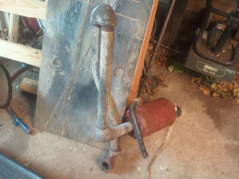
Any tricks or methods for tearing down assembled black iron exhaust pipe are appreciated. I have heated one area with mapp gas with no results. There is no rust visible at any of the threaded points.
James@(^.^)@ Ed
1977 Pearson P-323 "Dolce Vita"
with rebuilt Atomic-4
sigpic
Comment
-
-
I'd be putting a new one together as well...as mentioned, not worth the aggravation and the threads will be corroded.Mo
"Odyssey"
1976 C&C 30 MKI
The pessimist complains about the wind.
The optimist expects it to change.
The realist adjusts the sails.
...Sir William Arthur Ward.
Comment
-
-
exhaust design
Like everything else, this will be done from scratch. There is no space for the pictured design in my boat. The new design choices would:
1. run pipe directly from the manifold flange at a slightly downward angle towards the bulkhead at the front of the cockpit floor. The insulated hot pipe wold go through the bulkhead above and to the right of the shaft log, facing the rear of the boat. This is a run of about two feet. at this point, just beyond the bulkhead and in the vertical space there I would put my riser and injection point for the engine's water;
imagine a two foot straight run of pipe, then a 90 deg right for eight inches before the 12-15" of riser and water injection. Pretty much what I mocked up at Home Depot, with the pipe right after the manifold flange a full two feet instead of three inches
after this, I have to decide where to locate the waterlift muffler and the exhaust thru hull.
2. this version omits the riser entirely. The manifold sits above the water line, but only by an inch or so. Because the straight run of pipe goes directly under the cockpit floor, I would like to maintain the downward slope started at the manifold, to avoid any undue heating of the fiberglass floor unederlay.The downward sloping hot exhaust pipe would have the water injected a foot or so down the length of the insulated pipe, aiming towards the stern of the boat in the pipe. A section of exhaust hose would then connect the waterlift muffler to this wet exhaust hose. A loop or riser could be created for the wet exhaust hose after it exits the waterlift muffler.
Thoughts will as always, be appreciated.
JamesLast edited by Hymodyne; 04-17-2013, 11:29 PM.
Comment
-
-
James,
Here's some thoughts.
Your riser design is bulletproof, but there are two caveats:
1) Its a lot of weight. Too much to hang off of the exhaust flange. You'll need to get a couple of pipe hangers to support it.
2) Make sure to insulate the hell out of that long hot section! If you don't, all that heat eventually finds its way back into the cabin, making it very unpleasant in our humid Chesapeake summers!
If you go with the riserless solution, it sounds like your water injection point will be below the waterline. In this case it is absolutely critical that you insert a siphon-break valve in the water line before the injection point. Locate it as high as possible, in a place that will remain above the waterline at all angles of heel.
I would not recommend a loop in the exhaust hose after the waterlift muffler. Exhaust hoses are large diameter and stiff, requiring a large loop diameter. That would trap a large volume of water, with an attendant increase in exhaust backpressure, which is not desirable.
Instead, take the exhaust hose from the waterlift as straight up as you can manage, to a high point above the waterline, and then slope downhill all the way to the stern, with the through-hull exiting at a point that will always remain above the waterline.Last edited by edwardc; 04-18-2013, 07:36 PM.@(^.^)@ Ed
1977 Pearson P-323 "Dolce Vita"
with rebuilt Atomic-4
sigpic
Comment
-
-
fit
Originally posted by zellerj View PostI guess I don't understand why you want to replace it. From the picture in post 1 it appears to be in pretty good shape. It may have quite a few good years left in it.
Best,
Jim
I'd love to sell it, the minister of finance would like that
Ed, good advice, many thanks. I will probably install a riser and therefore have a two foot run of hot pipe, followed by a runs of eight, twelve, and four inch nipples, the parts of the riser before water injected, which will also need to be properly insulated and supported. Hangers? around the insulation, or around the pipe itself?
James
Comment
-
-
-
exhaust system
Got a little work done on the exhaust system today. picked up the T with a 1/2 reduction for the water injection, and finished installing the pipe and the loop:
the entire length of pipe from the flange on will get wrapped in muffler wrap.
I haven't found a place for the waterlift muffler yet.
suggestions as to where I should put it in relation to the rest of the system and the water line would be appreciated.
James
Comment
-
Comment