Rewiring my rats nest..

Collapse
X
 
  • Filter
  • Time
  • Show
Clear All
new posts
  • Mahoneymik
    Senior Member
    • Feb 2014
    • 32

    Rewiring my rats nest..

    I'm just starting my new project. The rats nest! I have a 1977 Catalina 30 with an Atomic 4 (not currently running , but that's another issue). None of the instruments that came with the boat work, and never have. It's time to tackle the big job.
    I have no electrical background at all, but I'm willing to put the time in to learn. I've been trolling the messages here, and I'm learning tons. I have the Moyer Marine handbook, "This Old Boat", "Sailboat Electrics Simplified", and just ordered "Boatowner's Mechanical and Electrical Manual".
    But I still have a few questions for the experts!
    These pics are the front and back of the instrument panel. The pic with the busbar is just to the left of the back of the instrument panel... It's a real mess.
    I'm wondering...
    What do you think of the instruments in the panel? Are they the right ones, or should I add/subtract some?
    As I replace the wiring, should I do one wire at a time, (or as I want, do I rip them all out and just start again from scratch?)
    Is it really important to get the ABYC color coded set, or can they all be the same color? I understand they should be labeled?
    Should I replace the old (probably original) instruments with shiny new ones? Expensive, but maybe worth it?
    I notice some wires just go from one instrument to the next, to the next, to the next... Is that correct?
    Anything else I'm missing, or should be asking?
    Sorry for all of the questions, but this is just the tip of the iceberg! If you know of any good posts that I may not have seen that might help, I'd really appreciate a link if that's possible. I hate to be the guy who asks the question when it's been answered for the thousandth time, but I feel like I need some specifics.
    Thank you for reading, and thanks in advance for any help you can offer!
    Attached Files
  • captainmurph
    Senior Member
    • Jan 2013
    • 35

    #2
    Originally posted by Mahoneymik View Post
    What do you think of the instruments in the panel? Are they the right ones, or should I add/subtract some?
    Oil pressure and temp working are a must. Fuel gauge is nice to have, as is the tach and ammeter. Oil pressure gauge is one of two types: One with a direct fluid connection to the oil gallery or one with a wire that goes to an electrical oil pressure sender. Water temp also has a sending unit with a wire to the gauge. In both cases, power is supplied to the gauge and goes to ground through a variable resistor (sending unit). If these don't work, check to see if there is power to them (with key on). If not, investigate and fix. That may be all you need to get these working. My guess is that the power which should be available from the ignition switch is not available. That would anwer why they all don't work.
    As I replace the wiring, should I do one wire at a time, (or as I want, do I rip them all out and just start again from scratch?)
    If you just investigate to get the existing gauges working, you can do them individually. But, if you start from scratch, make up a wiring diagram first!
    Is it really important to get the ABYC color coded set, or can they all be the same color? I understand they should be labeled?
    Not critical, but a very good idea. You can get nearly any color of primary wire by the foot in various sizes. Example here.
    Should I replace the old (probably original) instruments with shiny new ones? Expensive, but maybe worth it?
    If you decide to do this, look at vendors (WM, Defender, etc.) and note that there are "families" of identical gauges that you can get. Here's a family of SeaStar gauges at WM.. Once you decide what you ultimately want, you can buy the gagues and hook them up as time and new wiring permits.
    I notice some wires just go from one instrument to the next, to the next, to the next... Is that correct?
    That is likely the + feed from the ignition switch or the + feed for the lighting circuit on all gauges. The positive feed is usually only available in the key on position since the gagues are inoperative when the engine is not running. The lighting circuit is usually controlled by a switch or tied to the feed to the Navigation Lights so instrument lighting is always on when that circuit is active.
    Good luck. This is a big project but not as complicated as you might think. With the help of others here, you can get it done!
    Last edited by captainmurph; 04-08-2016, 07:33 AM. Reason: Duplicate Signature
    Greg Murphy
    S/V Amalia
    1965 Cal 30
    Muskegon, MI

    Comment

    • joe_db
      Afourian MVP
      • May 2009
      • 4527

      #3
      This is more tedious tracing and replacing wires than super-advanced electrical engineering.
      I take it we don't know if any of these gauges work. Tach, fuel, oil pressure, and temperature are good to have. There are a few threads on here about replacing the ammeter with a voltmeter, which is a very good thing to do. Also adding a manifold vacuum gauge is a nice addition.
      IIRC, Catalina used some crappy trailer connection in the wiring that causes endless issues. You may want to replace all that wire with new.
      Joe Della Barba
      Coquina
      C&C 35 MK I
      Maryland USA

      Comment

      • GregH
        Afourian MVP
        • Jun 2015
        • 598

        #4
        Ah those images and rat's nest look familiar!

        Mine is in a similar state but I've gone a gutted it and starting fresh. I am going to simply redo the whole wiring harness at one time to make it neat and tidy. As a shameless plug I'll be getting Moyers harness kit to simplify the acquisition process.

        There is a wiring PDF around the forum that shows the wiring and the jumpers from gauge to gauge, etc - that might be of help to see as an overview for you.

        You brought up a good point that I wasn't at yet... is there a way to test the gauges to make sure they work before wiring it all back together?

        Welcome to the forum!
        Greg
        1975 Alberg 30
        sigpic

        Comment

        • jbsoukup
          Afourian MVP
          • Jan 2012
          • 148

          #5
          Color coding with the proper colors is the best way to go.
          I would start by re-wiring the engine, leaving the gauges alone for now, to see if they work.
          Use heavy wire(8 gauge) for the start switch. it should be a white wire and a red wire running from the solenoid to the switch.
          I would also remove the ammeter wires (not the gauge just yet) and wire the alternator output (heavy orange wire) directly from the alternator to the + (red) terminal on the solenoid.
          Then just add new color coded wires for the temp, oil, fuel, ignition (coil), and tach.
          I found this diagram useful.http://www.moyermarine.com/forums/at...1&d=1460119956
          Attached Files
          sigpicjohn
          '77 catalina 30 #783
          the only way to be sure is to make sure

          Comment

          • joe_db
            Afourian MVP
            • May 2009
            • 4527

            #6
            Yes there is a way to test gauges. They work with 33-240 ohm senders. If you make a test rig with various resistors, 33 ohms should be one end of the scale and 240 the other. 240 would normally be the low end and 33 the high end. A simple rig would be a 33 ohm resistor in series with a 0-250 ohm pot if you can find one. Turning the pot should move the needle from one end of the scale to the other. Another way is a switch box with a few values, say 33, 50, 100, 200, 240.
            A side note - since the senders are ALL 33-240 ohms, it is possible to get some odd results. Swapping the temperature and pressure gauge wires would still "work", as would using a 100 or 150 PSI pressure sender on an 80 PSI gauge or using a 320 degree oil temp sender on a 240 degree water temp gauge.
            Speaking of senders, the senders can also be tested with an ohmmeter. An oil pressure gauge can be tested with air pressure and a temp sender tested to 212 degrees with water on the stove.
            Originally posted by GregH View Post
            Ah those images and rat's nest look familiar!

            Mine is in a similar state but I've gone a gutted it and starting fresh. I am going to simply redo the whole wiring harness at one time to make it neat and tidy. As a shameless plug I'll be getting Moyers harness kit to simplify the acquisition process.

            There is a wiring PDF around the forum that shows the wiring and the jumpers from gauge to gauge, etc - that might be of help to see as an overview for you.

            You brought up a good point that I wasn't at yet... is there a way to test the gauges to make sure they work before wiring it all back together?

            Welcome to the forum!
            Joe Della Barba
            Coquina
            C&C 35 MK I
            Maryland USA

            Comment

            • jbsoukup
              Afourian MVP
              • Jan 2012
              • 148

              #7
              Catalina used some crappy trailer connection in the wiring that causes endless issues. You may want to replace all that wire with new.[/QUOTE]

              yes, the only way to be sure. I was reluctant to do it but boy am I glad I did!
              sigpicjohn
              '77 catalina 30 #783
              the only way to be sure is to make sure

              Comment

              • Jim Bates
                Senior Member
                • Feb 2013
                • 15

                #8
                I did this project (and also rewired the entire boat).

                1. You indicate that your engine is not running. I would work on getting it running before you start rewiring. If you cannot get it to run, all your good work will have been wasted. If the engine is not running because it is not getting power, you will have to check each wire. The advice about getting a meter to check everything is good - you can check each wire to see if electricity is flowing or not. You have a 1977 so the wiring could be 39 years old and not conducting electricity.

                2. Get the MMI diagram DC Distribution Of Power to see how the engine wiring should be.

                3. Everything should be color coded according to ABYC standards. Also, go to Home Depot or Lowes and get yourself a number booklet from the electrical department. You can put a number on each connection and along the wiring so you know what wire goes where. If you need to rewire the engine wiring, you can buy a wiring harness with connections and other stuff from MMI.

                4. One of the things about the wiring is I see a lot of splicing. It is far better to use one piece of wire from connection to connection as opposed to splicing it in the middle. Down the road, you don't want to have your instrument not work and figure out you have a bad splice somewhere in the middle.

                5. Get yourself a bag of "Cable Tie Mounts". You will screw these into your bulkhead so you can secure your wiring with zip ties. You can get your zip ties at any hardware store. Neatness counts and will make life a lot easier. Secure loose wires together to avoid the rat's nest.

                6. When making connections, get yourself a heat gun and only use heat shrink connections when you can.

                7. You can check the gauges using a meter. If they don't work, you can buy replacement from MMI parts.

                These are just a few pointers. Good luck.

                Comment

                • ndutton
                  Afourian MVP
                  • May 2009
                  • 9776

                  #9
                  Many questions
                  • What is the goal of the rewiring project, get the instruments to work or undo the sins of the past, make it reliable, better than new?
                  • Is there a project budget?
                  • Pedestal steering or tiller? That may seem like an odd question but it addresses whether or not to relocate the instrument panel to a more visible location as part of the same project.
                  • What features do you want in the panel? Basic instruments or something more? Monitoring alarm?
                  • Is this a project you want to learn and do yourself or git 'er done by any means even if it's at someone else's hand? Same question another way, who will be doing the troubleshooting down the road?

                    edit: one more question
                  • What is the time frame/urgency for completion?
                  Last edited by ndutton; 04-08-2016, 06:03 PM.
                  Neil
                  1977 Catalina 30
                  San Pedro, California
                  prior boats 1987 Westsail 32, 1970 Catalina 22
                  Had my hands in a few others

                  Comment

                  • tac
                    Senior Member
                    • Nov 2015
                    • 210

                    #10
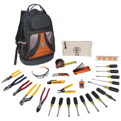
                    Tools

                    I am not an electrician, but have worked closely with marine and industrial electricians for over 50 years. I'm sure master electricians on the site will chime in.

                    If you're thinking about major work by yourself, you'll need the right tools.

                    Start by getting rid of this "tool", if you have one.


                    It supposedly cuts, strips and crimps. And it does none of these things well, IMHO (which is not H but is highly O'ed). This one is a Craftsman, but every hardware store and supermarket pedals one like it. Most of them are Junk.

                    Then get some good tools. I think (more HO) the best electrical hand tools are made by Ideal and Klein. You can find a small selection at Loew's (electrical dept):
                    Klein Tools is committed to American Manufacturing, since 1857. For over 160 years, Klein Tools has remained dedicated to professional tradesmen worldwide, with a commitment to manufacturing the world's finest hand tools right here in America. We don't just make great products, we make great products that stand up to the demands of the professionals who use them everyday.


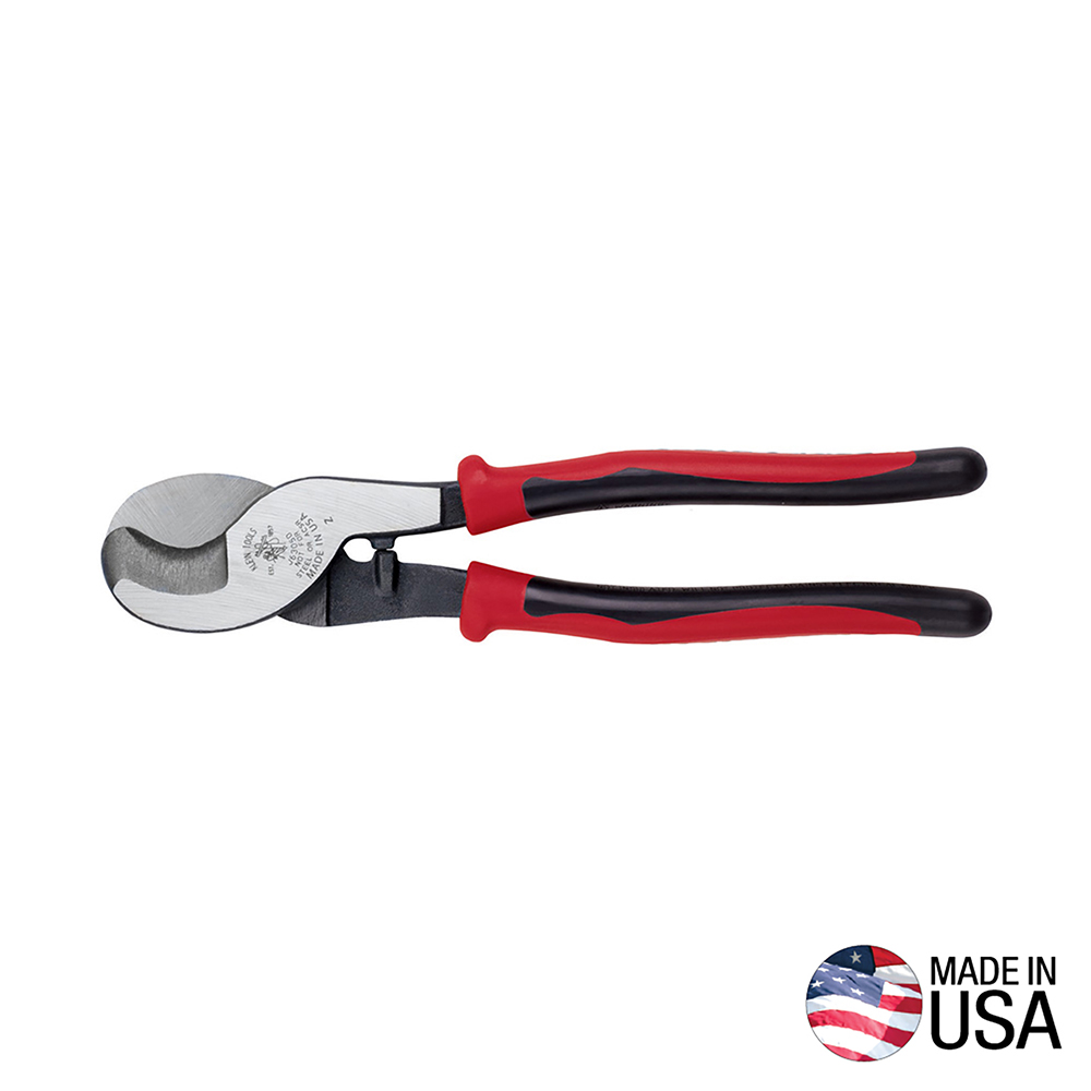
                    Cutters, for large wire and cable (optional):
                    Cut aluminum, copper and communications cable with the Klein Tools Journeyman™ Cable Cutter. Cable-gripping shear-type jaws provide exceptional cutting capability. Through-hardened, not case-hardened, cutting surfaces are longer-lasting.


                    Strippers:
                    Very expensive and generally overkill:
                    Klein Tools is committed to American Manufacturing, since 1857. For over 160 years, Klein Tools has remained dedicated to professional tradesmen worldwide, with a commitment to manufacturing the world's finest hand tools right here in America. We don't just make great products, we make great products that stand up to the demands of the professionals who use them everyday.


                    Cheaper and easier to handle and carry:
                    Klein Tools is committed to American Manufacturing, since 1857. For over 160 years, Klein Tools has remained dedicated to professional tradesmen worldwide, with a commitment to manufacturing the world's finest hand tools right here in America. We don't just make great products, we make great products that stand up to the demands of the professionals who use them everyday.


                    Crimpers:
                    Klein Tools is committed to American Manufacturing, since 1857. For over 160 years, Klein Tools has remained dedicated to professional tradesmen worldwide, with a commitment to manufacturing the world's finest hand tools right here in America. We don't just make great products, we make great products that stand up to the demands of the professionals who use them everyday.


                    Most hand crimpers will only crimp up to 10AWG wire. To crimp larger than that (#8 to 0000) you may need something like this, from Harbor Fright:

                    Comment

                    • JOHN COOKSON
                      Afourian MVP, Professor Emeritus
                      • Nov 2008
                      • 3501

                      #11
                      I agree with Captain Bates (post #8). Get the engine running first. Then you will know how much time, money, and effort you have left to do the rewire\gauge project. Boat projects have a strange way of getting more involved than planned............
                      In the meanwhile think about the questions in Neil's post (post #9). Several of the forum members have rewired the gauge\engine (me included) and can give you some pointers.

                      TRUE GRIT

                      Comment

                      • roadnsky
                        Afourian MVP
                        • Dec 2008
                        • 3127

                        #12
                        Agree with getting the engine running.
                        What is the condition of your battery (s)?

                        When you do decide to take the plunge...
                        I'd suggest also replacing the panel as well as the wiring and gauges.
                        The panel sold on this site is excellent and will provide you with a great backbone to build from.
                        I'd also encourage using properly colored wire but it's not a deal killer if you label well.

                        Here are a couple of pics of my re-wired panel plus the MMI DC Wiring
                        Attached Files
                        Last edited by roadnsky; 04-10-2016, 10:36 AM. Reason: Flipped pic for John
                        -Jerry

                        'Lone Ranger'
                        sigpic
                        1978 RANGER 30

                        Comment

                        • hanleyclifford
                          Afourian MVP
                          • Mar 2010
                          • 6994

                          #13
                          Your "rat's nest" is actually not as bad as many we have seen here. One thing you have not mentioned yet is the condition of your battery terminals and cables. In re-wiring that is where I would start, especially since the engine has not run for a while. Owning the right equipment for making up cables is an expensive proposition and I wouldn't recommend it unless you are a long range cruiser. I carry Felco ss cutters and a big NicoPress tool that also doubles as an emergency rigging kit. It's hard to get exactly the cable(s) you want since most set ups are unique. If you like I will make up cables for you from instructions for just about cost and shipping (since you are an Afourian). The advice about splicing mentioned above is sound, and plug in connectors mid run are a disaster waiting to happen IMO. Welcome.

                          Comment

                          • JOHN COOKSON
                            Afourian MVP, Professor Emeritus
                            • Nov 2008
                            • 3501

                            #14
                            Originally posted by roadnsky View Post
                            Agree with getting the engine running.
                            When you do decide to take the plunge...
                            I'd suggest also replacing the panel as well as the wiring and gauges.
                            I'd also encourage using properly colored wire but it's not a deal killer if you label well.
                            Wiring
                            Remember when you replace the gauges you will have to install new comparable sending units.
                            Actually your "rats nest" is pretty much par for the course in a boat that hasn't been rewired. The instrument cluster is remotely located so power and ground must be brought to it, if you want lighting. The usual way this is done is to bring power and ground to one terminal in the cluster then use short wires to to map it to other gauges, ignition switch,blower ect. If you stare at the "rats nest" long enough you will see how it works. It's easier to see in Jerry's picture - even though it's upside down.

                            TRUE GRIT

                            Comment

                            • ndutton
                              Afourian MVP
                              • May 2009
                              • 9776

                              #15
                              Last edited by ndutton; 07-12-2020, 10:41 PM.
                              Neil
                              1977 Catalina 30
                              San Pedro, California
                              prior boats 1987 Westsail 32, 1970 Catalina 22
                              Had my hands in a few others

                              Comment

                              Working...
                              X