Hot Coil and High Alternator Output

Collapse
X
 
  • Filter
  • Time
  • Show
Clear All
new posts
  • jpian0923
    Afourian MVP
    • Sep 2010
    • 976

    #16
    Neil, in your Ignition System Theory tests are you including Voltage at the + coil with your coil temp?

    It would be interesting to know if there was a correlation between the two.

    I'm suspecting that for a range of values there is a relationship.
    "Jim"
    S/V "Ahoi"
    1967 Islander 29
    Harbor Island, San Diego
    2/7/67 A4 Engine Block date

    Comment

    • ndutton
      Afourian MVP
      • May 2009
      • 9601

      #17
      Yes, primary coil input voltage is a datum but I'm not varying it in my theory or testing.

      It's pretty well accepted around here that reducing the primary input voltage reduces coil temperature. Some are achieving this with a ceramic ballast resistor ahead of the coil, others are tweaking their adjustable alternator regulators down - and affecting their battery charging I believe. I'm testing a theory as to why lower input voltage has this effect or more directly, are we making changes that don't really address the issue? That is, does the end justify the means? I intend to find out.

      I've enlisted the help of three other listmates so we'll have data from a variety of installations but one thing we all have in common is Pertronix electronic ignition.

      I'm not trying to be mysterious about it but there's nothing really to report until the testing is complete. Who knows, we may blow holes through the theory rather than support it but that's good information too. I'd prefer to report results as opposed to conjecture. Don and I have discussed it briefly off-list and he agrees that it should be interesting.

      Stay tuned - -
      Neil
      1977 Catalina 30
      San Pedro, California
      prior boats 1987 Westsail 32, 1970 Catalina 22
      Had my hands in a few others

      Comment

      • Triton106
        Senior Member
        • Jan 2009
        • 73

        #18
        Originally posted by hanleyclifford View Post
        If I seemed to be arguing against the use of electronic ignition, I apologize. These ignition systems are a proven workhorse and are rightly endorsed and sold by both Moyer Marine and Indigo. What troubles me is the use of such systems and the use of big alternators in the absence of accurate voltage control. My point seems to be this: If you have electronic ignition and a big alternator you are well advised to have a strong handle on voltage monitoring. This means a quality digital voltmeter that reads to hundredths of volts - like the Blue Sea models - not the multicolored analog toy sold by SW.
        Thanks Hanley, no need for apologies! Excellent point. However, my electrical system is so simple I only have one battery (I know it is heresy here). I used to have two group 27 plus a group 24 starting. But I never needed that much capacity with the type of daysailing that I do. So recently when the batteries need to be replaced I simplied it.

        Going back to my altnerator issue I plan to take it to a local alternator shop in Oakland and have them check it out. I believe that the regulator is shorted out (just a guess, my knowledge of alternator-regulator operations is non-existent eventhough I have a BSEE degree from an excellent engineering school which should remain anonymous to protect its reputation.
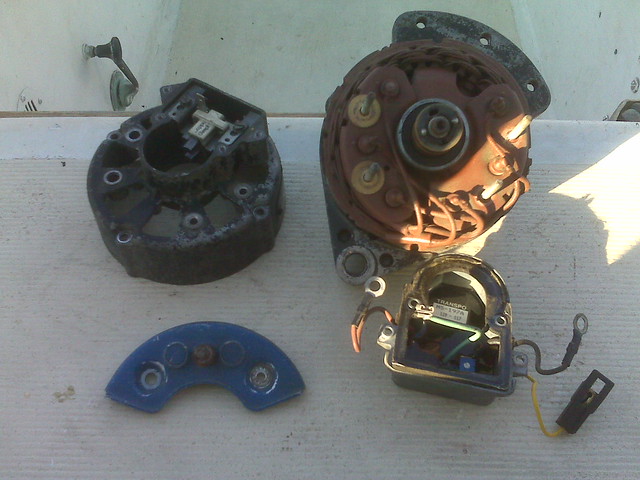
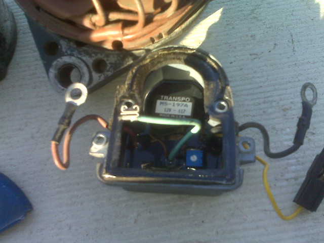
) The alternator shop has the Transpo M5-197 regulator in stock for about $38, which I believe it is a direct replacement. I will report back how that goes.

        Comment

        • smosher
          Afourian MVP
          • Jun 2006
          • 489

          #19
          Hey Triton a EE then this formula should ring a bell as they beat it into me 30 years ago

          peak volts = rms*1.414, so for your issue

          19.7= 14*1.414,

          since your reading 20 volts instead of 14 the diodes have no voltage drop,
          hence the shorted diodes.

          Steve

          Comment

          • sastanley
            Afourian MVP
            • Sep 2008
            • 6986

            #20
            Triton..that m5-197 is the same regulator I have, & that price seems reasonable. A diode plate at the local alternator shop was about $15.

            The only issue with that regulator is it is completely potted, so you have to remove the regulator from the alternator to get to the little adjustment screw in the back to adjust the output voltage. It is a little touchy to dial in..not tedious, but it might take two or three tries to get it where you want it. I didn't think it was prudent to adjust while running, so I unmounted and remounted mine each time and tweaked the screw in 1/4 turn increments.

            What I've personally done is gotten my charging voltage dialed in at the batteries to where I want it (whereas I was WAY over-charging before..detailed elsewhere on the forum in my own failed coil thread), and as Neil noted (BTW, I am one of his guinea pigs...er..."test subjects" , related to providing various coil data.) - I currently have a 1.4 ohm ballast resistor blocking some voltage to the new 1.5 ohm coil, as recommended by a Pertronix tech. Additionally, I have a new 3.0 ohm coil and the old failed 3.0 ohm Pertronix coil available for testing all of Neil's various theories..I agree...it should be interesting.

            [off topic]
            However, I've been a bit slow in reporting back to him. We've been a bit busy here cleaning up from Lee & Irene (the insurance adjuster finally visited yesterday to discuss repairs to my damaged garage roof from Irene) & trees are either still being felled on purpose to avoid future damage, or ones already on the ground are still being cut up...just not much time for intricate boat diagnostics at present, but I'll get to it here as things slow down (yeah, right.. ).
            [/off topic]

            At any rate..I personally like the Transpo regulator...I think I just had mine set too high for a while.. - Hanley's recommendation to have a good voltmeter aboard to check the voltage at various spots in the circuit is key..I printed out a copy of my electrical schematic and recently notated voltages at various locations (coil, battery(ies), isolator, common post, etc.) to help with diagnostics. It helped me to lay out a picture of the charging circuit in action.
            Last edited by sastanley; 09-20-2011, 09:12 AM.
            -Shawn
            "Holiday" - '89 Alura 35 #109
            "Twice Around" - '77 C-30, #511 with original A-4 & MMI manifold - SOLD! (no longer a two boat owner!!)
            sigpic

            Comment

            • ndutton
              Afourian MVP
              • May 2009
              • 9601

              #21
              No rush on my tests Shawn. I haven't had the time to get past the first barrage either. Maybe this week. Maybe.
              Neil
              1977 Catalina 30
              San Pedro, California
              prior boats 1987 Westsail 32, 1970 Catalina 22
              Had my hands in a few others

              Comment

              • Triton106
                Senior Member
                • Jan 2009
                • 73

                #22
                Originally posted by smosher View Post
                Hey Triton a EE then this formula should ring a bell as they beat it into me 30 years ago

                peak volts = rms*1.414, so for your issue

                19.7= 14*1.414,

                since your reading 20 volts instead of 14 the diodes have no voltage drop,
                hence the shorted diodes.

                Steve
                Steve, it's been a while and I am way out of my comfort zone here. I think you are probably right. Can you just replace the diodes in the regulator or do I need to replace the whole thing? This is just for my curiosity I plan to take the alternator to a local shop as mentioned above and have them test it out.

                Comment

                • smosher
                  Afourian MVP
                  • Jun 2006
                  • 489

                  #23
                  Hi Triton, you could just replace the diodes, but there could be other failure modes in the regulator assembly.

                  I would replace the whole assembly and call it a day

                  Steve

                  Comment

                  • Triton106
                    Senior Member
                    • Jan 2009
                    • 73

                    #24
                    Wow, that is a fast response!

                    BTW, Steve, in addition to the orange wire that I see on Moyer's wiring diagram there is yellow a wire that hangs out of the regulator and goes through a fuse and connects (red wire after fuse) to coil + terminal. Is that a sensing wire or what is it?

                    Comment

                    • sastanley
                      Afourian MVP
                      • Sep 2008
                      • 6986

                      #25
                      Triton,

                      It is my understanding the diode plate & the regulator are separate 'bolt on' pieces, obviously with a little wiring going on underneath.

                      the two shiny parts in this picture are the diode plate (top) & the regulator (big thing with 4 screws)

                      -Shawn
                      "Holiday" - '89 Alura 35 #109
                      "Twice Around" - '77 C-30, #511 with original A-4 & MMI manifold - SOLD! (no longer a two boat owner!!)
                      sigpic

                      Comment

                      • roadnsky
                        Afourian MVP
                        • Dec 2008
                        • 3101

                        #26
                        Originally posted by Triton106 View Post
                        ...in addition to the orange wire that I see on Moyer's wiring diagram there is yellow a wire that hangs out of the regulator and goes through a fuse and connects (red wire after fuse) to coil + terminal. Is that a sensing wire or what is it?
                        Triton-
                        The yellow wire is the EXCITER TERMINAL to the coil.

                        "Connect the EXC terminal to the positive terminal of the coil using a 14 gauge wire so that the fields of the alternator
                        will be excited when the ignition switch is turned on"


                        Here's a pic of my old Moto 35 Alt with the Exciter Wire off the regulator...
                        Attached Files
                        Last edited by roadnsky; 09-20-2011, 01:59 PM.
                        -Jerry

                        'Lone Ranger'
                        sigpic
                        1978 RANGER 30

                        Comment

                        • Triton106
                          Senior Member
                          • Jan 2009
                          • 73

                          #27
                          Shawn, Jerry, Steve, everyone, thank you so much. I will post the outcome of my alternator investigation.

                          Comment

                          • Triton106
                            Senior Member
                            • Jan 2009
                            • 73

                            #28
                            Ok, the hunt continues...

                            Today, I first looked up the actual model number on the alternator plate and it is MR12N550. I could not find any product detail data on the unit since they are discontinued. However, I found through cross reference on Prestolite Website

                            I then took the alternator to a local shop in Oakland (Buchanan Auto Eletrical) since they have the M5-197 regulator. The first thing I asked them to do is to bench test the alternator which they did. The test result, however, shows that the output voltage is 14V rather than the 18-20V I have been getting on the boat. They also said the current output is 30A which it should be putting out 60A. I was surprised to learn that the alternator, although a Motorola unit, is not the original 35A model and they guessed the output should be 60A. In addition, they said tha the unit is too hot. They said that since it is putting out 14V the regulator is sound.

                            I asked them what else could cause the output to be 18-20V on my boat and why the output current is lower than what they expected. They said the only thing they can do is to open it up and rebuild it which will cost around $180.

                            So, I took it back to my friend Rob's shop and took the unit apart to visually inspect if there are any obvious physical signs of damage (eg. loose or broken wires, burn mark, etc...) Here are the pictures which as you can see do not suggest any obvious damage.


                            So, I put everything back together. Suspecting that my multimeter may not be caliberated properly I borrowed Rob's digital multimeter. Back on the boat I put the alternator back in and reconnected the wires. After double checking the wiring I fired up the A4 again. Again, I tested the voltage output but with Rob's digital unit. This time it shows 17.2V on the positive side of the coil. The negative side shows 9.4V. That is clearly still way high on the positive side. Is the negative side voltage right? What should it be?

                            Judging by the outcome of Bradley's experience (see Alternator Output > 18V the shop test outcome is not always reliable. I am guessing that my regulator is also the cause of the problem.
                            Last edited by Triton106; 09-22-2011, 01:44 AM.

                            Comment

                            • roadnsky
                              Afourian MVP
                              • Dec 2008
                              • 3101

                              #29
                              Triton-
                              Do you want my old 35 Motorola?
                              It was working fine when I changed it out last year for the 55.

                              Yours if you want it. Just pay the shipping.
                              -Jerry

                              'Lone Ranger'
                              sigpic
                              1978 RANGER 30

                              Comment

                              • smosher
                                Afourian MVP
                                • Jun 2006
                                • 489

                                #30
                                Interesting, looking at the pictures is the red wire insulation cracked by the case ? Could be a shadow.

                                When you measure the vdc, try the ac scale, that will tell you if there's an ac component in the voltage for the + side of the coil.

                                The voltage output from the alternator is changed from ac to dc by the diodes.

                                I tried looking for a schematic but couldn't find one. I would assume that it uses the exciter wire to also sense the voltage and to drive the regulator, less voltage, higher output. I would check and or replace the yellow wire connector which goes to the + side of the coil.

                                The neg side of the coil goes to the points in your distributor, this is what conducts the current flow through the coil. This would be a ac voltage in rhythm with the points opening and closing.

                                Looks like the regulator was already replaced as the transpo was used.

                                If the 17 vdc was on the battery then the battery life will be shortened.

                                Steve

                                Comment

                                Working...
                                X