Delco Alt/internal Voltage Regulator poor output

Collapse
X
 
  • Filter
  • Time
  • Show
Clear All
new posts
  • JackConnick
    Senior Member
    • Nov 2004
    • 168

    Delco Alt/internal Voltage Regulator poor output

    I have an Islander 28 that I use for cruising.

    I have a Delco 70amp alternator on my late model A4. It's in good shape, just had a shop look it over. Wiring is single wire, plus sense - decent condition and sized well, I believe.

    I have a house bank of two Group 27 105 amp flooded batteries, plus and another Group 27 isolated as a starting battery in reserve. My daily use is about 18-20 amp hours

    I have a meter on the system. My problem is the internal voltage regulator.

    When I start out it goes up to 27 amps, about what you'd expect. Voltage is about 13.1v. But it drops to 16 ah after about 1/2 hour, and after any hour or so down to a paltry 3-4 amps output. Voltage goes down to about 12.8v.

    I'm trying not to get into a huge expense, but I'd like to improve the output to replace about what I use in a day in maybe an hour, which is well in the range of the alternator I have.

    I read that you can have a shop convert it to an external regulator, but those regulators seem expensive $200-$375 or so? Is there a good inexpensive solution?

    But is there a replacement internal regulator I could add? It seems like a lot of these new alternators run at something like 14.4v? But at what amp output for how long?

    Or should I look at other areas, changing the ground around or something to trick the regulator into better output?

    TIA,
    Jack
  • joe_db
    Afourian MVP
    • May 2009
    • 4474

    #2
    Your alternator or installation are defective in some way. The regulator might be the issue, but it also might be something else.
    The Delco 10si and the myriad copies of it are very common alternators, so any competent alternator shop should be able to check it for you. It is possible to convert one to external regulation, I did it to a 10si knockoff I got from FleaBay. It is also possible to install any number of relatively cheap regulators in them with various setpoints.
    Can you give us some detail and maybe photos of how this is wired? Where does the output wire go and what gauge is it? Can you describe the sense wire and where it goes? I am familiar with 3 wire 10si alternators and 1 wire, but I cannot recall a 2 wire setup.
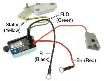
    This is an external adjustable regulator for the 10si series:
    Delco 10Si, 12Si, and 15Si conversion regulator. Converts the normally B-circuit 10Si, 12Si, and 15Si to A-circuit regulation. Self-exciting and stator activated.

    I didn't use that, I did my own wiring kluge to bring the field out. In the end my alternator lost some diodes and the output got low, kind of like what you have now. That also could be one of your issues.
    Our host sells alternators too, FYI
    Last edited by joe_db; 04-13-2020, 06:10 AM.
    Joe Della Barba
    Coquina
    C&C 35 MK I
    Maryland USA

    Comment

    • ndutton
      Afourian MVP
      • May 2009
      • 9601

      #3
      My thoughts pretty much parallel Joe's with a few twists. Disclaimers: I do not know exactly what your meter is supposed to read and I do not know how it is connected into your system.
      1. As near as I can tell, your alternator amperage output is functioning as I would expect. That is, higher charge rate to start then tapering off as the battery charge comes up. Remember, it is the battery's need that determines the charge rate, not the alternator's rated output. As the battery charge comes up, its need is less therefore the charge amperage is less.
      2. The alternator voltage output as reported is low but that may be a result of the installation. Exactly where is the output voltage being measured, at the alternator output post or somewhere else downstream? This is where wire gauge, wire length and amperage come into play. I like to see something around 14.0~14.2V at the battery.
      3. As for the alternator's rated output amperage, don't expect to see it with our engine's RPM. The maximum I've ever seen on mine is around 75% of rating and it was only briefly.
      Last edited by ndutton; 04-13-2020, 09:09 AM.
      Neil
      1977 Catalina 30
      San Pedro, California
      prior boats 1987 Westsail 32, 1970 Catalina 22
      Had my hands in a few others

      Comment

      • JackConnick
        Senior Member
        • Nov 2004
        • 168

        #4
        It's a single wire alternator. The output wire is pretty heavy gauge (I'll have to look at size again) and goes to an idolator, then splits to the batteries.

        It has the two wires off the back, I'll check that run.

        The meter is on the batteries, probably around 13.4-5v at start, I'll check.

        The one thing is that the main grounding wire is run to the transmission case cover bolt. I know Moyer likes it run to the starter mounting bolt, I haven't had a chance to change it, as I need a longer cable. Could that make that much of a difference?

        It seems to me that the voltage regulator is simply an automotive style and old, just needs to be better.

        Moyer is out of stock of the 120 amp API, and I don't think API is making it any more, can't find the right part on their website? And that's $375.

        But the Delco 10si 105 amp alternators are dirt cheap - around $60-65:
        DB Electrical keeps your vehicle running with premium aftermarket auto parts, including replacement alternators, starters and more.


        But I wonder what kind of voltage regulator it will have.

        For that cost it seems like screwing around repairing this old alternator is not even worth the trouble. In these days of shop closures, even getting a new cable is hard.

        I'll run down and take a look at the wires and measure the voltage off the alternator and batteries, take a couple of pics and report back.

        Comment

        • joe_db
          Afourian MVP
          • May 2009
          • 4474

          #5
          Originally posted by JackConnick View Post
          It's a single wire alternator. The output wire is pretty heavy gauge (I'll have to look at size again) and goes to an idolator, then splits to the batteries.

          It has the two wires off the back, I'll check that run.

          The meter is on the batteries, probably around 13.4-5v at start, I'll check.

          The one thing is that the main grounding wire is run to the transmission case cover bolt. I know Moyer likes it run to the starter mounting bolt, I haven't had a chance to change it, as I need a longer cable. Could that make that much of a difference?

          It seems to me that the voltage regulator is simply an automotive style and old, just needs to be better.

          Moyer is out of stock of the 120 amp API, and I don't think API is making it any more, can't find the right part on their website? And that's $375.

          But the Delco 10si 105 amp alternators are dirt cheap - around $60-65:
          DB Electrical keeps your vehicle running with premium aftermarket auto parts, including replacement alternators, starters and more.


          But I wonder what kind of voltage regulator it will have.

          For that cost it seems like screwing around repairing this old alternator is not even worth the trouble. In these days of shop closures, even getting a new cable is hard.

          I'll run down and take a look at the wires and measure the voltage off the alternator and batteries, take a couple of pics and report back.
          I think you mean ISOLATOR, not "idolator"
          If that is the common diode isolators, you usually lose around half volt in those, plus or minus a bit. This is one reason they have fallen out of favor and relay type combiners with no voltage loss have taken their place.
          You do not have a 1 wire alternator if three wires come out of it. The three wire 10si alternator has the following:
          1. Output
          2. Sense
          3. On/Off and light

          This is the common setup in a car:


          If you have a diode isolator, the sense wire needs to be on the far side of it!
          Can you trace those smaller wires and tell us where they go? Also please tell us what kinds of meters you have and where they are connected. The ground wire is likely fine, many installations skip it. I would move it to wherever the battery ground wires connect to the engine though.
          Lastly, please be careful of buying a cheap 10si. The cheapest ones will not have the marine spark shield. The sort of cheap ones that do have that are not all that long lasting when run hard. Mine was under $100 and lasted probably 30 hours before it got sent to the dumpster, so say around $3/hr to use the thing
          Joe Della Barba
          Coquina
          C&C 35 MK I
          Maryland USA

          Comment

          • ronstory
            Afourian MVP
            • Feb 2016
            • 404

            #6
            Originally posted by JackConnick View Post
            I have an Islander 28 that I use for cruising.

            But is there a replacement internal regulator I could add? It seems like a lot of these new alternators run at something like 14.4v? But at what amp output for how long?

            TIA,
            Jack
            If you believe your regulator is on the fritz, you can buy just the regulator with a different Vset.


            I'm using a DB Electrical AMN0002 and its Vset is 14.4V and is marine rated. I came with nice card showing it's tested performance vs RPM and Vset value.
            Thanks,
            Ron
            Portland, OR

            Comment

            • ndutton
              Afourian MVP
              • May 2009
              • 9601

              #7
              Originally posted by joe_db View Post
              You do not have a 1 wire alternator if three wires come out of it. The three wire 10si alternator has the following:
              1. Output
              2. Sense
              3. On/Off and light
              Joe, what Jack described in his opening post is how my previous Delco 10Si was wired. It started its life as a true single wire and a shop added an excite wire. Without the excite wire connected to anything it would perform as it did (came to life with a bump in RPM) but connecting the excite wire to the starter solenoid 'R' terminal would get it producing immediately without the RPM bump.

              Mine was actually a 3 wire but very different from your drawing. The 3 wires were output (the original single wire), excite as described above and AC tap for the tachometer pulse (diesel style).
              Neil
              1977 Catalina 30
              San Pedro, California
              prior boats 1987 Westsail 32, 1970 Catalina 22
              Had my hands in a few others

              Comment

              • JackConnick
                Senior Member
                • Nov 2004
                • 168

                #8
                I went down to the boat and poked around.

                It's a 3 wire Delco. I 8 guage wire up to the older Isolator. Looks like about a 12 gu. up to the battery switch (I believe). The other to the neg lead of the coil bussed

                Main bank 2x Grp 27 105 amp hour batteries at rest were full and 13.4v, checked at the battery.

                I started it up ran it at fast idle for a few mins. and the voltage at the battery (after iso) was 14.2v. The output was only 2 amp, but the batteries were already full.

                I measured the voltage right at the alternator and it was 15.3v!

                So I don't know, this alternator was adapted and I suspect it has an internal automotive voltage regulator. Another Delco might help I guess, but it seems like it's sending volts.

                It sounds like a new isolator might be a good idea. But doubt it would make a difference to charging? Any ideas on makes?

                See photo, I have leads from the charger going to both batteries. One lead from the engine.

                I just replaced the battery charger with a very nice Mastervolt 20 amp charger, that really zaps these. We tend to be at a dock around every 3-4 days and the boat is plugged in when not in use.

                I just added a icebox conversion kit that is very good on electricity, maybe 2 amps or so when it runs, which isn't much during the night. Otherwise it ramps up when the engines is running. Same with forced air Wallas heater.
                Attached Files

                Comment

                • ronstory
                  Afourian MVP
                  • Feb 2016
                  • 404

                  #9
                  Originally posted by JackConnick View Post
                  .

                  I started it up ran it at fast idle for a few mins. and the voltage at the battery (after iso) was 14.2v. The output was only 2 amp, but the batteries were already full.

                  I measured the voltage right at the alternator and it was 15.3v!
                  Depending on where your current shunt is located in the wiring, thing could be better or worse. I'll shoot for the worse side of the dial. ;^)

                  Assuming you are using the same ground location and are losing 1.1V between the alternator and the battery with only 2A going through the wire, you need hunt down the voltage drop. It could be a bad connection(s) or wire with higher resistance due to a bad crimp or corrosion. Are any of the wires getting warm to the touch?

                  Now on the better side of the dial, it appears you sense wire and your voltage regulator are working.
                  Thanks,
                  Ron
                  Portland, OR

                  Comment

                  • JackConnick
                    Senior Member
                    • Nov 2004
                    • 168

                    #10
                    Well the isolator is the biggest answer it seems. The wires all look good and are newer. Is 8 guage large enough?

                    Jack

                    Comment

                    • joe_db
                      Afourian MVP
                      • May 2009
                      • 4474

                      #11
                      Diode isolators cannot help but cause a voltage drop, that is what diodes do. That is why your sense lead should go to the battery.
                      Here is a suggestion:
                      Run the engine at cruise RPM.
                      Make sure the battery charger is off.
                      Turn on all your lights. All the cabin lights, running lights, anchor light, and so on. I have an inverter and I use that to create heavy loads with a heater, so that is something else for a high current test. Note you are unlikely to get much more than 50 amps out of ANY alternator on an A4 with the stock pulley setup.

                      Measure the voltage to ground at these points:
                      1. Alternator output.
                      2. Input terminal of the isolator. (where the alternator connects)
                      3. Output terminals of the isolator.
                      4. Positive terminals of the batteries.

                      Some of that wiring in your photo looks like it has cracked insulation or other dubious connections, you also might want to look at that. IMHO 8 gauge wire is a bit light, I use 4 gauge myself, but it isn't too bad. Many boats seem to get by with worse.
                      Joe Della Barba
                      Coquina
                      C&C 35 MK I
                      Maryland USA

                      Comment

                      • ronstory
                        Afourian MVP
                        • Feb 2016
                        • 404

                        #12
                        Joe has some great points on where to test. My first thoughts would be to just loosen, wiggle and re-tighten all the connections and then remeasure.

                        8 gauge is a bit on the small side. How long is the length of 8 gauge wire?
                        Thanks,
                        Ron
                        Portland, OR

                        Comment

                        • JackConnick
                          Senior Member
                          • Nov 2004
                          • 168

                          #13
                          Moyer says 8 gauge, based on 80 amp max. for the run up to the isolator.
                          I'm guessing it's only about 8'. Some of what you're seeing is just paint. But I'll check the connections. I can certainly check the sense wire, maybe upgrade it. I'm trying to stay out of the stores right now though, and cut wire can't be ordered.

                          I agree with the load test idea, I didn't have time yesterday. I'll check it andf report back.

                          I think I may just go ahead and replace the isolator anyway. I like the Mastervolt products.

                          But that won't change the voltage regulator tapering off amps too soon? Just that it might charge a bit faster?

                          Jack
                          Last edited by JackConnick; 04-14-2020, 08:23 PM.

                          Comment

                          • JackConnick
                            Senior Member
                            • Nov 2004
                            • 168

                            #14
                            OK, just back from doing a bunch of testing...

                            Batteries were at overnight rest at 12.6v. -0.1 ah.
                            I checked connections and cleaned them, all is good. I moved the (12 gauge) sense wire to the batteries (it was on the output of the isolator, so it really didn't make any difference).
                            -----
                            Put on everything in the boat for quite a while and ran them down:
                            Batteries were at -28ah, 12.3v, 85% full (meter off batteries)
                            -----
                            Started up and ran it up in gear at about cruising revs.

                            After 5 mins:

                            Alternator output: 14.4v, Output was 17.4ah.
                            Input at Isolator: 14.23v (almost no loss)
                            Output at Isolator: 13.3v (big voltage loss there)
                            Batteries at 13.2v (might of been 13.3 if I pressed harder)

                            Still had the full 18ah load from the boat on it. Turned boat load off. Output went up a little to 19.4ah.
                            -----

                            After 15mins:
                            Batteries were at -25.3 ah, 13.3v.
                            Output was 15.2 ah
                            Alternator was at 14.5v

                            So the isolator is definitely an issue. But if I understand things that really only means that I will get a little faster charge for the first 30-45mins, I guess. I need amps, not necessarily volts.

                            The alternator is still ramping down amp output quickly after about 15-20 mins. I expect that it will do exactly what it did the other day and after 1.5 hrs be at 3ah output.

                            So is my only alternative to replace the alternator with an expensive Balmar setup at $800 or so? The new isolator is like $275.

                            TIA,
                            Jack

                            Comment

                            • JackConnick
                              Senior Member
                              • Nov 2004
                              • 168

                              #15
                              Does anyone have any experience with this isolator:
                              Cole Hersee Smart Battery Isolator 85A

                              Comment

                              Working...
                              X