Help Identifying Alternator and rebuild/replace

Collapse
X
 
  • Filter
  • Time
  • Show
Clear All
new posts
  • Neuse River Sailor
    Senior Member
    • Aug 2017
    • 24

    Help Identifying Alternator and rebuild/replace

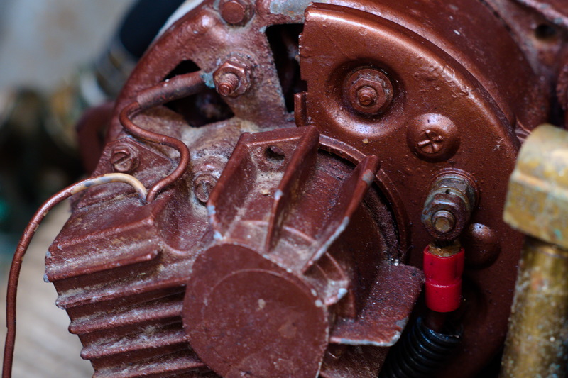
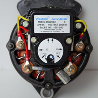
    Hi All - My battery is not getting charging voltage from the alternator. I removed the alternator and took it to a shop. The mechanic said that a diode in the regulator is blown and that he is unable to find the diode in his catalog. He said he might have more luck if he had some identification of the alternator. Can anyone identify this alternator, off a late model Moyer rebuild from 2009?


    The boat had a starting battery and a house battery, but the house battery faulted and I removed it altogether.

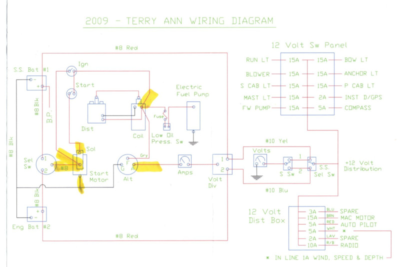
    The diode may have blown from being routed to the faulted battery before I removed it, but looking at the wiring diagram it appears to me that the alternator output goes to an isolator and then is routed to both batteries without going through the A-B switch. A friend with much more electrical ability than me checked the resistance through the isolator and said he thought it was defective. He suggested that I remove the isolator and tie the three red wires to the isolator together.


    If I can get the alternator repaired I would like to. Or, buy a new one from the Moyer site, if it will drop in place of the old one. Or, beg, borrow or steal a small gas generator to keep the battery charged enough to get me to the Pamlico Sound where there are Atomic 4 mechanics who can fix my charging system. I have not been able to find anyone to do the work at my present location on the upper Albemarle Sound.

    Any advice appreciated...
  • Don Moyer
    • Oct 2004
    • 2806

    #2
    Alternator

    Hello Neuse River,

    In 2009 we were still using rebuilt Motorola alternators that were standard on all late model Atomic 4s from the 1970s. The only history we have as to the cause of output diode failures is from running the alternator to an open circuit (like with the battery selector in OFF). As far as I know, the output diodes were pretty standard on all that vintage of Motorola, so I'm a bit surprised that a local starter/alternator shop was not able to match them up for you and install a new set. The only advise I can think of - other than to replace the alternator - is to try and find another local automotive starter/alternator shop for a second opinion, or go back to the one you already went to and try to tactically find another person to talk to. You may have gotten a counter person that was having a bad day and you simply didn't have his/her full attention. Meanwhile, I'm hoping that some senior Forum member with a better handle on electrical issues than I will come to your rescue with some solution that I'm simply not aware of. Don

    Comment

    • Neuse River Sailor
      Senior Member
      • Aug 2017
      • 24

      #3
      Thanks, Mr. Moyer, that may help us out a lot. The mechanic is a good and knowledgeable man but he's distracted by some serious health issues that his wife is having, and anything I can do to make his work easier will help. Knowing that it is a Motorola unit might trigger his memory. He says he has a source in the midwest that sometimes has parts for vintage alternators and maybe they can supply the diode.

      If anyone else wants to lend guidance, I'm ready to listen.

      fair winds
      NRS

      Comment

      • ndutton
        Afourian MVP
        • May 2009
        • 9601

        #4
        Sounds to me like a good time to upgrade to a new, higher capacity alternator instead of repairing the old one.
        Neil
        1977 Catalina 30
        San Pedro, California
        prior boats 1987 Westsail 32, 1970 Catalina 22
        Had my hands in a few others

        Comment

        • tac
          Senior Member
          • Nov 2015
          • 209

          #5
          Motorola Alternator MR12N451D

          Prestolite Leece-Neville bought out Motorola’s line of alternators a few years ago. Yours is probably a 37 amp model MR12N451D. The Prestolite web site is not easy to navigate, but the parts list for this alternator can be found at:


          For another online source for parts, you might try:
          High Output Alternators built right in the USA. We also have parts, upgrades, kits, marine and industrial units, guides, instructions, and more.

          Comment

          • Al Schober
            Afourian MVP
            • Jul 2009
            • 2006

            #6
            From your description, it's not clear to me whether the alternator or the regulator has failed. The purpose of the regulator is to send current to the field windings in the alternator. If the regulator has failed (no current to field windings), you can bypass it and send current to the field through a toggle switch. In essence, YOU become the regulator - turn on field current when battery voltage gets low, turn it off before you cook your batteries.
            One of the early external regulators was the AutoMac (sold by Weems & Plath) which I used for years. It had two controls - an ON/OFF switch and a current adjustment. It would charge at the current you selected until the battery came up to voltage, then shut itself off. In use, I would then dial back the current a bit and restart the regulator.
            Last edited by Al Schober; 05-15-2019, 10:53 AM. Reason: AutoMac info.

            Comment

            • Neuse River Sailor
              Senior Member
              • Aug 2017
              • 24

              #7
              Thanks for the responses. With that parts number, the mechanic has found a replacement for me. In his opinion, the cost of the diodes and labor would be close enough to the cost of a new alternator to make it better to just replace the whole thing. So he is ordering one and will have it for me next week. He will show me how to hook it up, in comparison to the old one.

              Since I removed the isolator on suspicion that it was not working correctly, I have three red wires to tie together - a positive from the house battery, a positive from the starting battery, and a positive leading to the alternator. Can I put in a toggle switch with the two positives from the battery on one side, and the positive to the alternator on the other, to make a field disconnect switch, so I can turn the current to the alternator off when the engine is not running?

              Comment

              • tac
                Senior Member
                • Nov 2015
                • 209

                #8
                No. Most toggle switches are rated at no more than 10 amps. If you mean one wire is from the alternator output (you said “to the alternator”) then that can carry, and switch, the full alternator output. With your Motorola alternator that is 37A. A 10A toggle switch might last as long as several milliseconds before its contacts melted or vaporized. If you get a higher output alternator, you will need a switch that can safely handle switching the higher output, something like,

                300 Amps continuous rating for outboards and small gasoline or diesel engines.

                Comment

                • Neuse River Sailor
                  Senior Member
                  • Aug 2017
                  • 24

                  #9
                  Tac, I have just one red wire on my alternator, attached next to the + sign as shown in the photo I posted of the alt. I am proposing to put a toggle rated for 20 amps at 125 volts which I think should be safe for around 200 amps at 12 volts where the isolator used to be, with the lead between the alternator and the toggle on one side and the two leads to the battery positives on the other. What do you think? Would that be a usable plan? My concern is that with the direct connection between the batteries and the alternator, I could see battery voltage at the alternator all the time, even with the engine shut down and the A-B switch in the off position.

                  Comment

                  • tac
                    Senior Member
                    • Nov 2015
                    • 209

                    #10
                    Alternators

                    If you would like to know how alternators work, possible places that discuss this include:

                    What is an alternator? We answer this question in detail, giving you the theory and components to understand how your alternator generator works.


                    The best, and most understandable however, is Nigel Calder’s book Boatowner’s Mechanical and Electrical Manual, well worth $20:


                    In short, an alternator’s output is controlled by regulating (changing) the current to the field windings. This is done two ways:

                    1. A “regulator” is included as part of the alternator. This is what you have. The regulator senses the battery voltage and uses a small(ish) current (0-5A or so) to the alternator’s field windings. The lower the field current, the lower the output current from the alternator (stator current). The alternator’s output, the stator current, is 3 phase AC, and is then converted to DC inside the alternator, generally using a bridge rectifier (6 or more diodes - “rectifier” is merely a 4 syllable word for the 2 syllable “diode”). In your case, the regulator is behind the finned retangular metal piece in your first photo. The two #16 (or so) wires coming out of that finned box (one is/was white, the other is now copper) are connected to the alternator’s field winding via carbon brushes (P/N 14) to a set of internal slip rings (P/N 18), at that nut.

                    2. The alternator has no built in regulator. You buy a regulator and connect its output to the alternator’s field winding terminals. The external regulator senses battery voltage and adjusts the field current, 0-5A, to control the alternator output.

                    In your case, the Motorola alternator output is a #8 (red) wire to the battery(s) + terminals through the ammeter and something called a “Volt Div”, which I guess is someone’s attempt at describing an Isolator, and a battery selector switch. A #8 wire is rated, for an engine space, at 68 amps. This is sufficient for the 37A alternator.

                    What Al was describing was eliminating any alternator internal regulator, and controlling the alternator output directly from the battery using a switch. In the control system world this is called bang-bang control, since the alternator output is switched on and off, rather than smoothly controlled over the full field 0-5 amp range. This used to be the standard way on cars, before about 1970, to regulate alternator output, using a voltage sensitive relay (regulator) on the firewall which contained a set of contact points that would switch the field current on and off. The John Luckless regulators on English cars were notorious for these contacts burning out every few thousand miles.

                    If you want to convert an internally regulated alternator to an externally regulated one, it ain’t difficult - see:

                    Many boats, specifically sailboats, come equipped with, or have have used, the 5" small-case Motorola/Prestolite/Leece-Neville style alternator. There are literally thousands of these out there. This style alternator is now being manufactured by Leece-Neville. The 8MR series, pictured here, are spe


                    Finally, to answer your specific questions....

                    Switch ratings are NOT linearly scaleable. A switch rated at 20A @ 12VDC is NOT therefore rated at 200A at 120VDC. If the manufacturer does not specify, the rating for a 20A 12VDC switch would be 2A at 120VDC. It’s related to the power the switch can handle (volts x amps). To complicate it even more, a switch rated at 12VDC is often rated at a lower current at 12VAC. Likewise, your switch rated at 20 amps at 125 volts (probably AC) is highly unlikely to be rated at 200A DC. I’d be surprised if it were even rated as high as 20ADC. In short, always check the manufacturer’s data sheet, or ask them.

                    For an easy tutorial on switches, see:


                    Your plan is to switch the alternator’s output off with a manual switch on the #8 red wire. That will certainly disconnect the alternator from the battery, but when you switch the alternator’s output off with the engine running, the output at the alternator stator momentarily goes VERY high, generally high enough to destroy one or more diodes in the bridge rectifier, which reduces the alternator’s output to an .....ummm......unusable level. If you are correct that the “isolator” is defunk-it, then if it internally failed open circuit, it probably caused the alternator’s rectifiers to fail (go BOOM!).

                    Your concern about having battery voltage at the alternator output when the engine is off is no problem. That’s how the great majority of cars and boats are wired. The diodes in the bridge rectifier (if good) will only see battery voltage, less than 14VDC, or so. These diodes usually have a reverse voltage rating of over 100 volts, and so isolate the battery from the alternator, until the alternator’s output exceeds the battery voltage (i.e. the engine is running). Moverover, many alternators include an “isolation” or “blocking” diode right after the bridge rectifier. It’s purpose is to further isolate the alternator from the battery. If I ‘member right, the Motorola has this diode (P/N 11).
                    Last edited by tac; 05-16-2019, 05:12 PM.

                    Comment

                    • Neuse River Sailor
                      Senior Member
                      • Aug 2017
                      • 24

                      #11
                      Thanks, Tac - I can see that the alternator output - the red positive wire - goes through an ammeter to what this schematic calls "volt div" which I agree must be the isolator - then from there to the batteries. So I can dispense with the "volt div" and tie those three red wires together and the alternator will send current to the two batteries?

                      "Your concern about having battery voltage at the alternator output when the engine is off is no problem" - OK, that's good, I don't have any need to put a toggle switch, which I have seen called a field disconnect switch, anywhere in the circuit.

                      One thing that is confusing me is looking at the schematic and it looks like the Selector Switch is not between the alternator and the batteries. It looks like the only thing the selector switch does is control whether one or the other or neither or both batteries supply voltage to the starter. But I won't worry about it unless I need to.

                      So my plan will be to install the new alternator and wire it just like the old one, but dispense with the isolator, tying the three red wires together. Then I should be able to set the Selector Switch to the fully-charged starting battery, start the engine and put a multimeter across the battery terminals and see the alternator output.

                      If I'm missing something or getting ready to harm the electrical system, please let me know. If I can get this boat back to the Pamlico, I'll have a competent mechanic go over the engine and get it in shape. As you can see, mechanical/electrical is not my forte. Thanks again for your patient help.

                      Comment

                      • ndutton
                        Afourian MVP
                        • May 2009
                        • 9601

                        #12
                        A drawing would really help
                        Neil
                        1977 Catalina 30
                        San Pedro, California
                        prior boats 1987 Westsail 32, 1970 Catalina 22
                        Had my hands in a few others

                        Comment

                        • roadnsky
                          Afourian MVP
                          • Dec 2008
                          • 3101

                          #13
                          Originally posted by ndutton View Post
                          A drawing would really help
                          Should we suggest something like this?
                          Attached Files
                          -Jerry

                          'Lone Ranger'
                          sigpic
                          1978 RANGER 30

                          Comment

                          • Neuse River Sailor
                            Senior Member
                            • Aug 2017
                            • 24

                            #14
                            I did post the schematic at the beginning of the thread. The only thing I'm proposing to change is, the device labelled "Volt Div", that has one wire coming from the alternator and two wires going out to the batteries, to tie all three wires together and delete the "Volt Div" which Tac and I both think is the defective isolator.

                            Comment

                            • tac
                              Senior Member
                              • Nov 2015
                              • 209

                              #15
                              I think you understand this, but let me emphasize it. Your setup, with the Motorola alternator, or any alternator with a built-in regulator, does NOT allow you to connect wires to the alternator field. There are no terminals for you to connect to the field winding. That is because the alternator’s internal regulator connects there internally. So, don’t even think about connecting from the battery to the alternator field via a switch, or anything else.

                              Blue Sea Systems catalog (http://pod.delzer.com/powerproducts/bss_cat/) has a lot of useful information on their products, and some simple illustrations with cute drawings.

                              For example, pg 32 shows some of their manual battery switches. One of these is probably what your “sketch” calls “Sel Sw”. When properly wired, it allows you to select which battery, #1 or #2, is connected to the house/engine loads and alternator (like the 6008), or OFF. Roadnsky’s post shows such a setup.

                              Your switch may have a ”Both”, or “1&2”, position (6007), allowing both batteries to be connected together. This, from your description, appears to be what you’re aiming for.

                              All these are manual switches, and are generally used to switch between two similar batteries on a daily rotation, to give equal usage and charge.

                              If you connect the 3 wires going to the “Volt Div” together, the alternator output will always go to both batteries. While that will work, you won’t be able to disconnect the alternator and house loads from the batteries when in the OFF position. This is a safety thing - in event of a fire or emergency, you’d like to put the switch in the OFF position and disconnect everything from the batteries and alternator. The alternator output and the house loads should be connected to the selector switch’s COMMON terminal (which may or may not be the unnumbered terminal in your sketch), as shown on pg 32.

                              On Pg 40, Automatic Charging Relay (ACR) and Isolators, is shown how an ACR is connected to do this switching automatically, and how an Isolator is hooked up. From your sketch, you appear to have an Isolator (dead or alive).

                              The catalog appendix on pg 160, Battery Management Schematics for Typical Applications, shows some common connections with an ACR. Yours may be the one labeled “2 Battery - 1 Engine”. (As part of a marketing philosophy of “don’t confuse the customer, he’ll buy more”, they don’t show an alternator. Instead you get an engine).

                              Comment

                              Working...
                              X